In the beginning.
In the post on the creation of a web application to interact with the arduino, in the end it was better to go for a wifi module of the ESP family thanks to it uncoupling with the pc, the opposite being a nuisance most of the time.
Intro to Solid State Relays
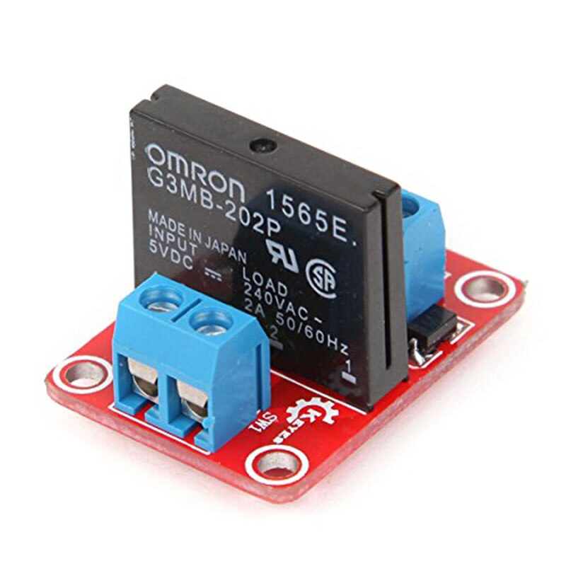
For complex circuits of alternating voltage and fast switching we have the solid state relays, available ready to use, with the main components such as triac, octocouplers, with zero crossing which are ideal for circuits with induction, and with encapsulated with professional finishes.
Some of them are as follows:
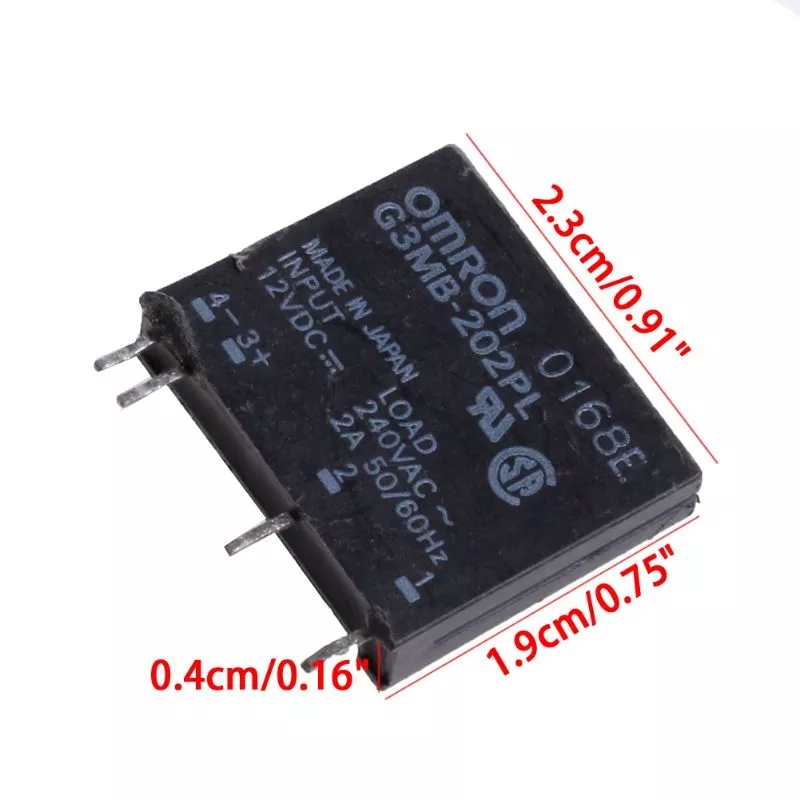
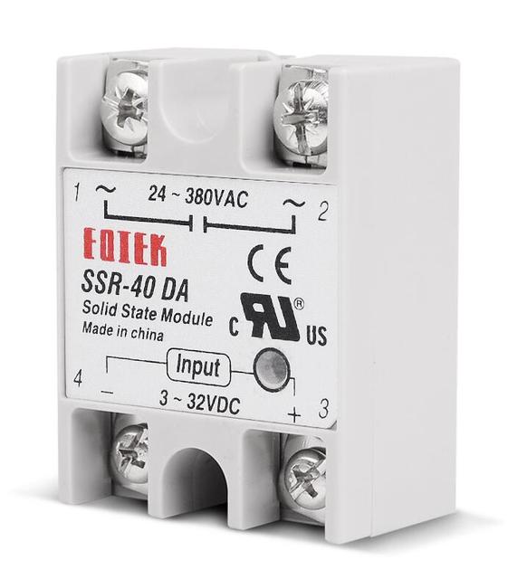
This one is about 40Amp
Being activated with about 5vdc from a microphone.
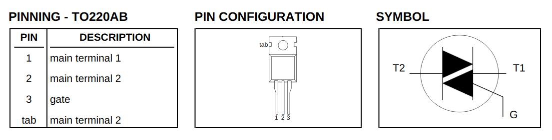
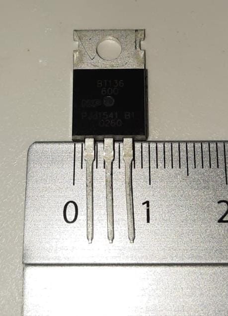
TRIAC BT136
It allows us to handle alternating voltage 220v AC~ and up to over 400v AC~ in controlled situations.
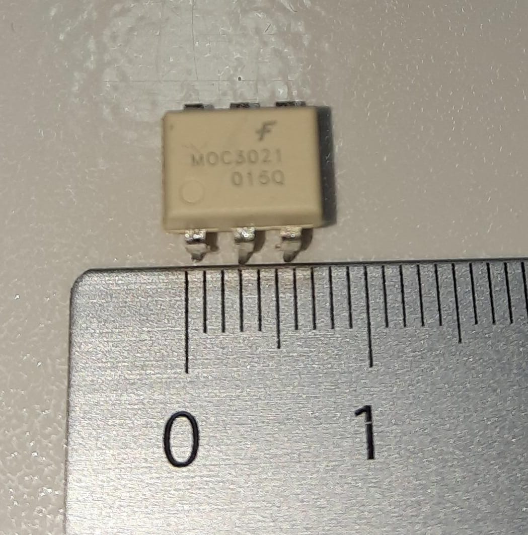
Octocoupler MOC3021
This model does not have the zero crossing or zero crossing, but it is very useful too, we could use a relay for it, but the moc to own taste is cooler, adding that many variants are used, in other types of circuits, since inside this model has a led that is activated with a small voltage, according to its datasheet:
| INFRARED EMITTING DIODE | SYMBOL | VALUE | Unit |
|---|---|---|---|
Reverse Voltage |
VR |
3 |
Volts |
Forward Current — Continuous |
IF |
60 |
mA |
Are 3v and 60mA maximum supported, but 15mA could work, this voltage activates another internal triac.
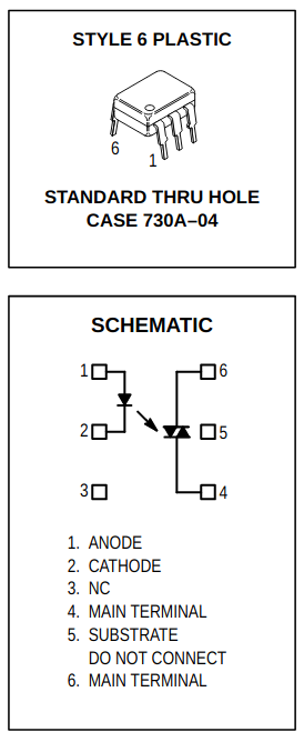
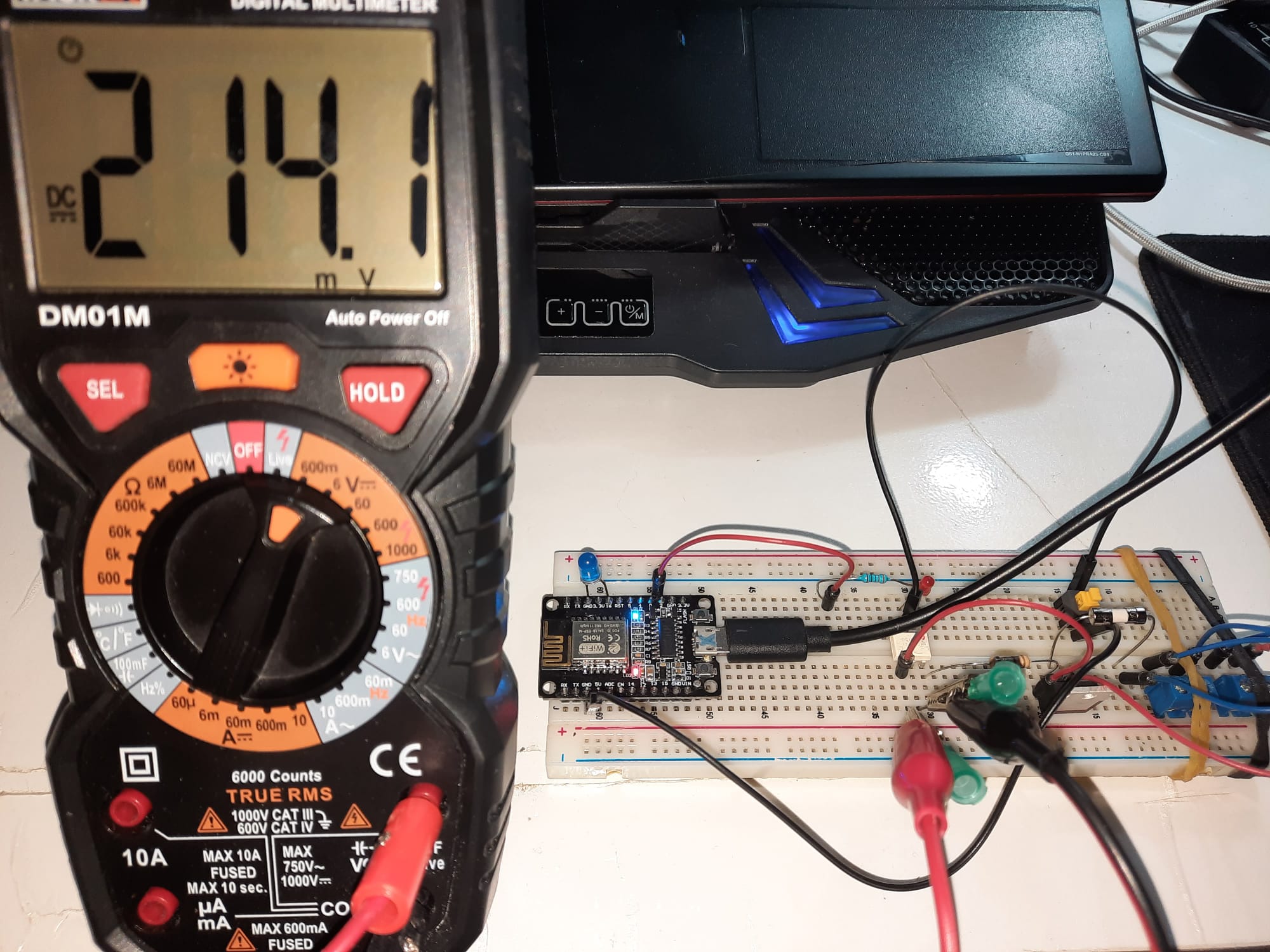
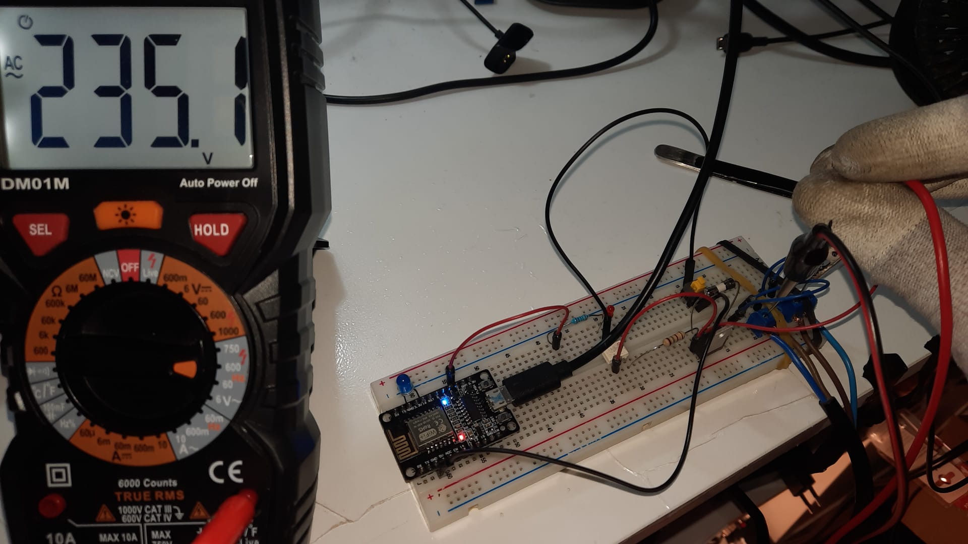
When damaged, pin 1 (anode) and 2 (cathode) should not have continuity, apparently when it receives voltage in the previous pins, in pins 4 and 5 you get a measurement of 200mV approximately as in the image below, it must be well connected on the breadboard.
It is small, and the through hole version measures less than 1cm.
Circuit design on the breadboard
In order for us to be able to turn on a light/bulb etc., we need both the triac and the octocoupler to work together.
|
Flow between TRIAC and OCTOCOUPLER
|
| The octocoupler when we include it allows us to separate the DC and AC voltage part, of course, it is still dangerous if you do not do things carefully, you have to be very careful to know by heart the connection (ie the phase and neutral where they are always not to touch them). |
Operating video
Right now, the application code, written with Vaadin Flow 14 is being refactored, currently what is there is this.
You can see that the button in Google Chrome consumes to an endpoint in my local network, this endpoint is thanks to the asynchronous web server of the NodeMCU.
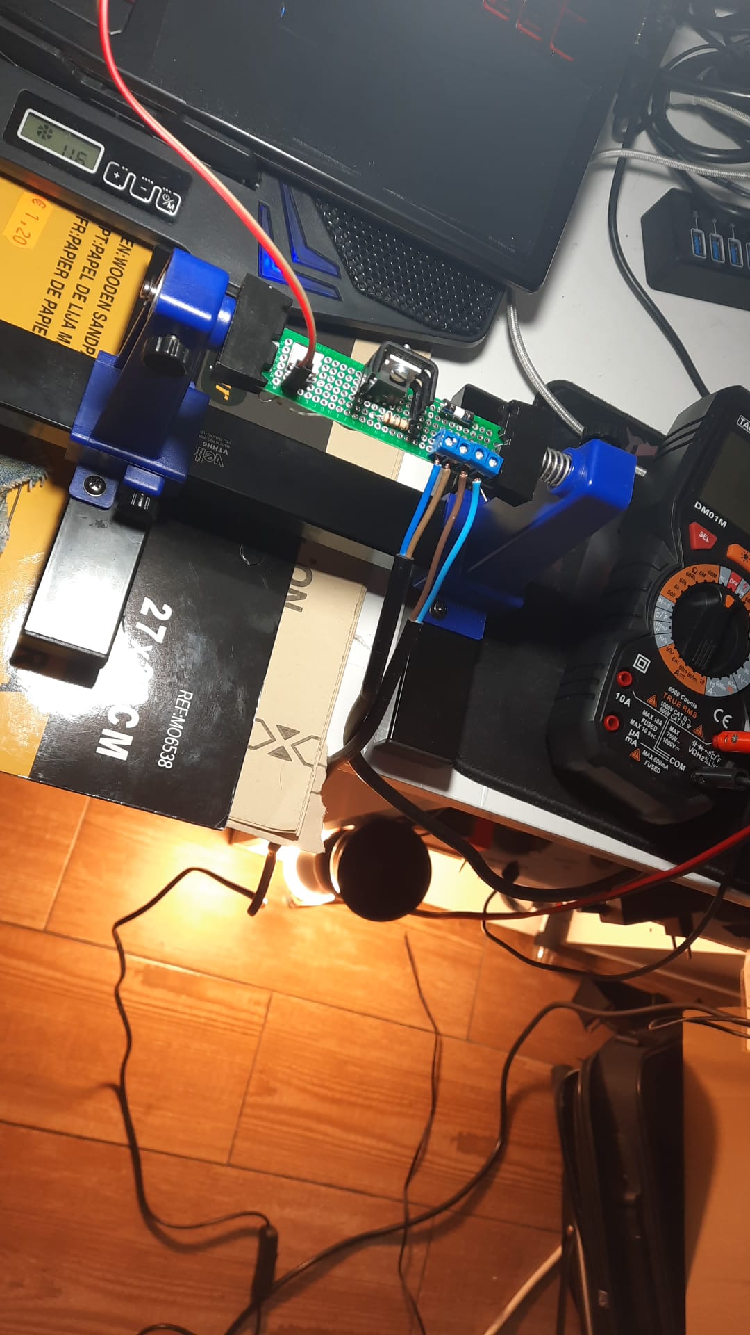
Using a simple, small prototyping board
It is really interesting to go a little further, with the prototyping board and soldering the components correctly we have a good result, on the recommendation of Carlos Luis Espinoza my cousin, I am encouraged to include a 2A FUSE in one of the lines, in such a case and by joule effect if there is much heating, the fuse will be damaged, ie the lead wire that contains internally melt, preventing the circuit components are affected, adding also that our load is a simple light bulb.
| You should always have the AC voltage and the load connected before placing the microphone, so that the arc voltage is not generated (which has happened to me several times by connecting the AC voltage last, producing a short circuit, which lowers the house breaker). |
Operating video
There are times when the NodeMCU does not start and it is due to the ground, by soldering a switch in normally closed mode, I can make the ground disconnect for a second and press the reset button of the NodeMCU and get it to start.
| Something very interesting, depending on the load of the bulb, when we turn it off we usually see a slow shutdown, with an incandescent bulb as in the video, but if you switch to an RGB, LED etc. the shutdown is done immediately. |
EasyEDA
It is a quite useful software to design (schematics, PCB) with a UI already quite worked and intuitive to use, once we have our design ready, with the same company of the app, we can manufacture our board with the soldered components if we want.
There is an online version easyeda.com/editor in which we can login via Google Sign-In, quite convenient because we can share our designs with people all over the world and reuse them equally, also keep our designs in offline mode (if we download the desktop app).
- Busqueda de componentes en EASY EDA
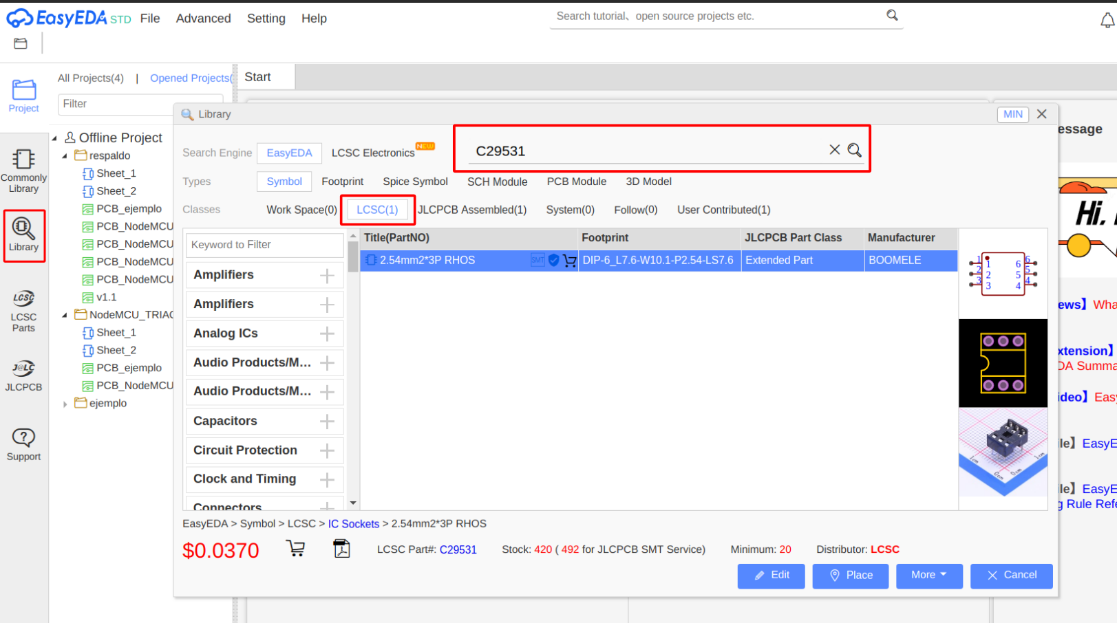
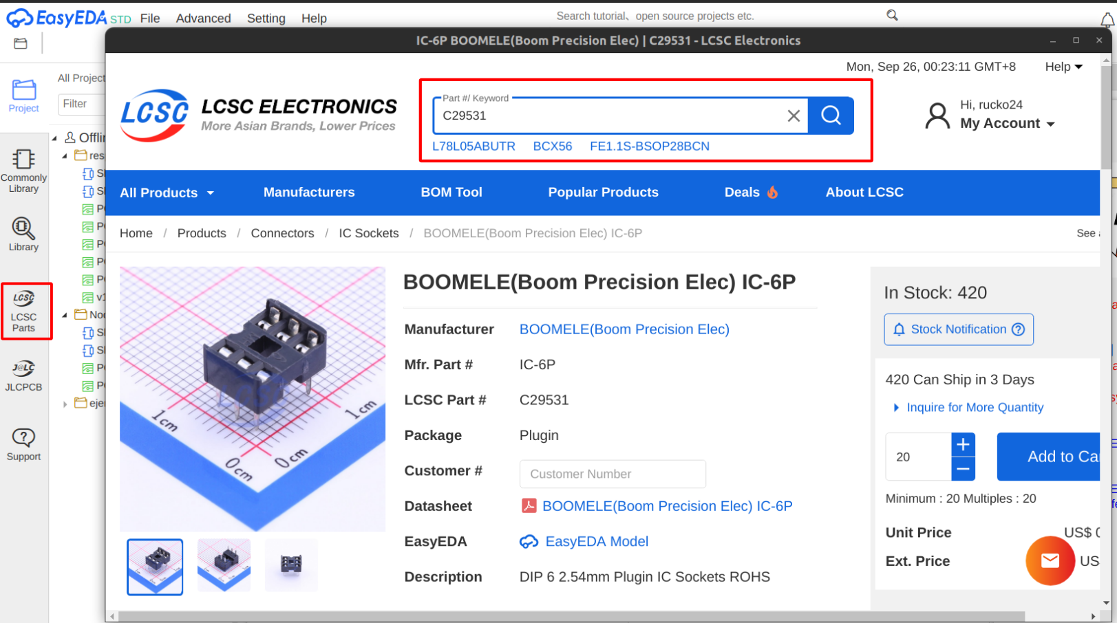
Searching for components both offline and online, is easy as it consists of a large library, in several ways can be done, one of them and useful is, The JLCPCB Part is like the serial of that component for example:
IC 6-pin socket your JLCPCB Part is:
-
C29531
| Here searching with the desktop app, both "Library and LCSC Parts" would help us to identify our component. |
As you can see the format in which it works is .json and the PCB Fabrication File (Gerber) this is the last step with our board ready, if we pass all the connections, this being a step prior to obtaining the .gerber, we are enabled to download a .zip with everything related to our gerber, which are actually a set of files more.
Visualizing the electrical schematic
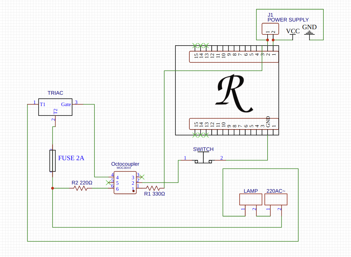
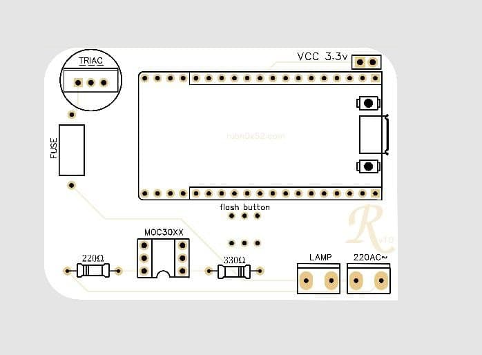
This is our wiring diagram, highlighting in brief the following:
Female pins to VCC and GND of the microphone so that an external power supply can be connected.
The Switch which is connected to the GND pin of the microphone and pin 2 of the octocoupler.
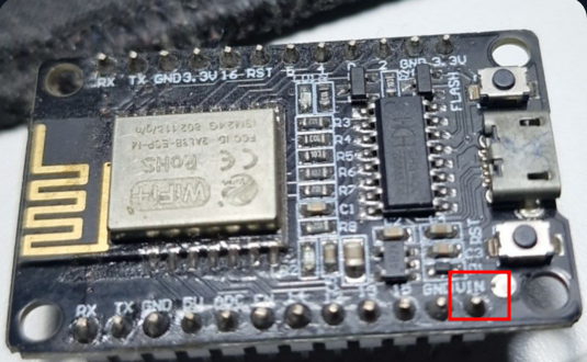
| Aquí se puede ver que los pines 1, no estan en buen punto, los esp82xx contienen un pin llamado VIN propio y es un pin de entrada de voltaje que permite alimentar la placa desde una fuente externa, normalmente entre 5V y 12V (aunque el rango exacto depende del regulador de voltaje integrado en la placa, suele ser hasta 12V máximo para la mayoría de las NodeMCU). |
Corona Effect
In the PCB part he directly draws the lines different from 90º avoiding to do the (Corona discharge).
If you do not want to paint the lines by hand, there is the auto route in the top menu, very useful to do it quickly. Este es un modelado 3D que nos permite tener una idea de como quedaría nuestra PCB, bastante cool.
The following image is intended to design a PCB with pins to insert the NodeMCU and extract it whenever you want to program it or even leave it connected thanks to the flash button added to the PCB, if when trying to flash it does not connect, then simply press the button achieving disconnection to ground/GND to enter the UART mode.
Not bad I would say, for a first version, the next one will come with improvements, this manufacturer allows us several colors, I used white.
Assembling the final prototype
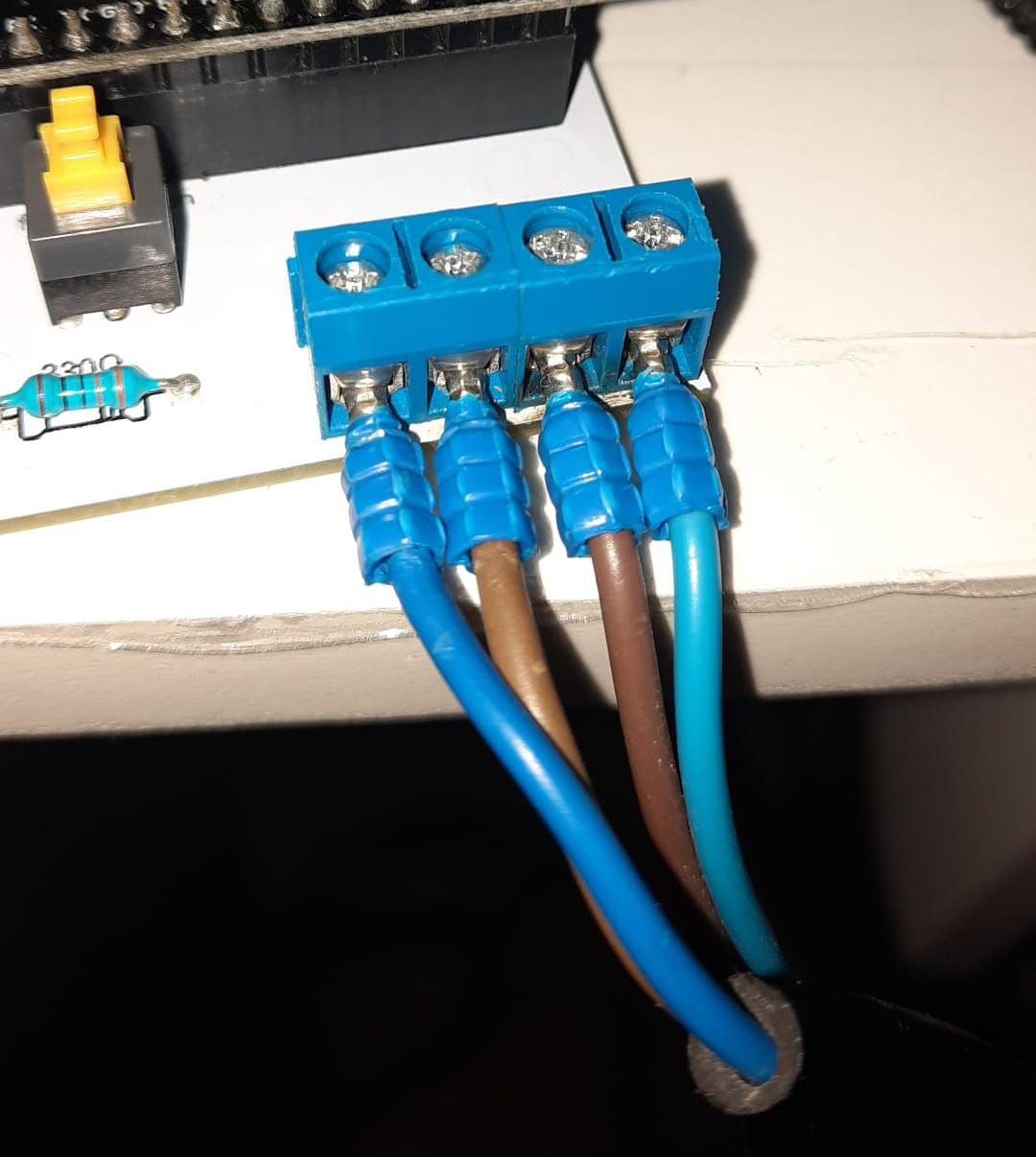
If there are some things to improve, such as separating the terminals more, adding warnings on the power part, fixing several names, a black logo etc…
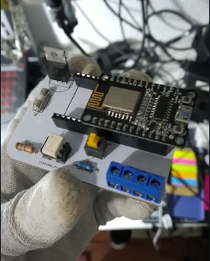
| Now the tip of the wires that go to the terminals comes very well a hexagonal plier and round pins, also avoiding the random short-circuit of here. |